Building a Paul Gartside #130; a traditional 12 ft clinker-built sailing dinghy.
Part 1
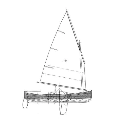
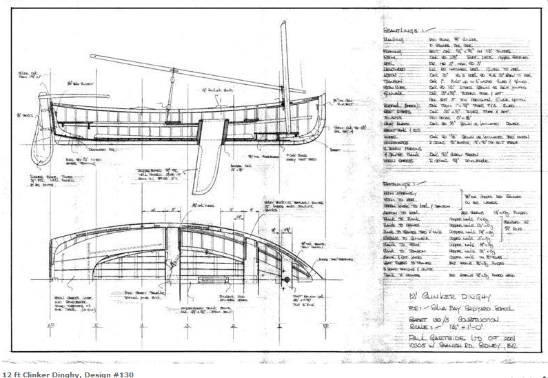
I was wanting a new boatbuilding challenge, something that would test my woodworking skills to the limit and keep me engrossed for a lengthy period. I also wanted a craft that I could enjoy in the company of my dog, with us both occasionally sleeping aboard. For those reasons I chose a sailing dinghy with a traditional solid-wood clinker-built construction. The size was selected as being small enough for me to keep it under cover at home, light enough to manoeuver on my own, but just big enough to carry kit for multi-day adventures. These criteria led me to the 12 ft Paul Gartside design #130.
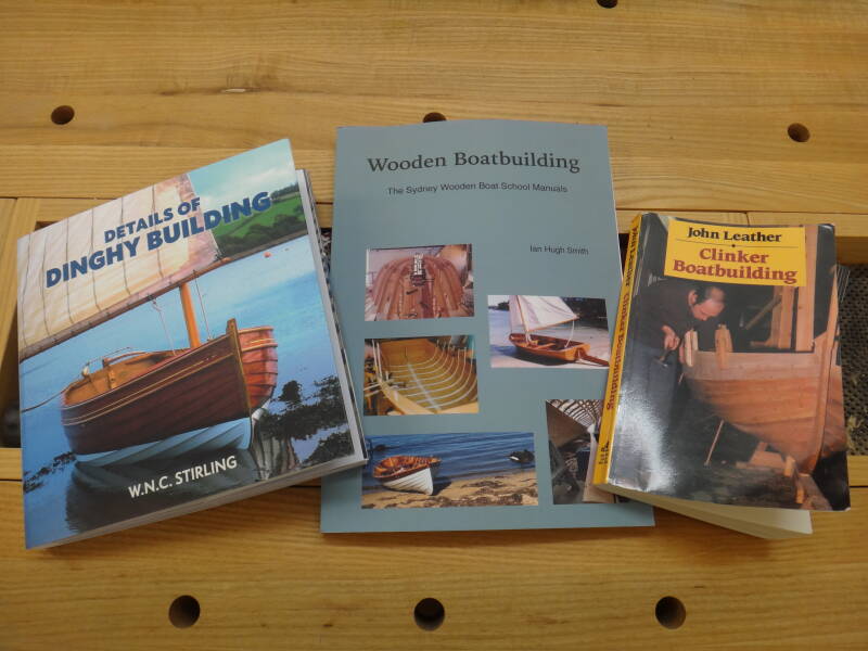
I purchased the paper plans and spent some time studying them, while also reading several books on clinker-built boat construction; John Leather's book from the 1970's, Ian Smith's book from the Sydney Wooden Boat School, and Will Stirling's beautifully illustrated book 'Details of Dinghy Building'. It took me a while to understand the new vocabulary and get my mind round the processes and stages involved. There are, of course, many different ways to do things and I often had to choose the option I thought would be easiest for me to achieve, from the widely differing advice offered.
Lofting
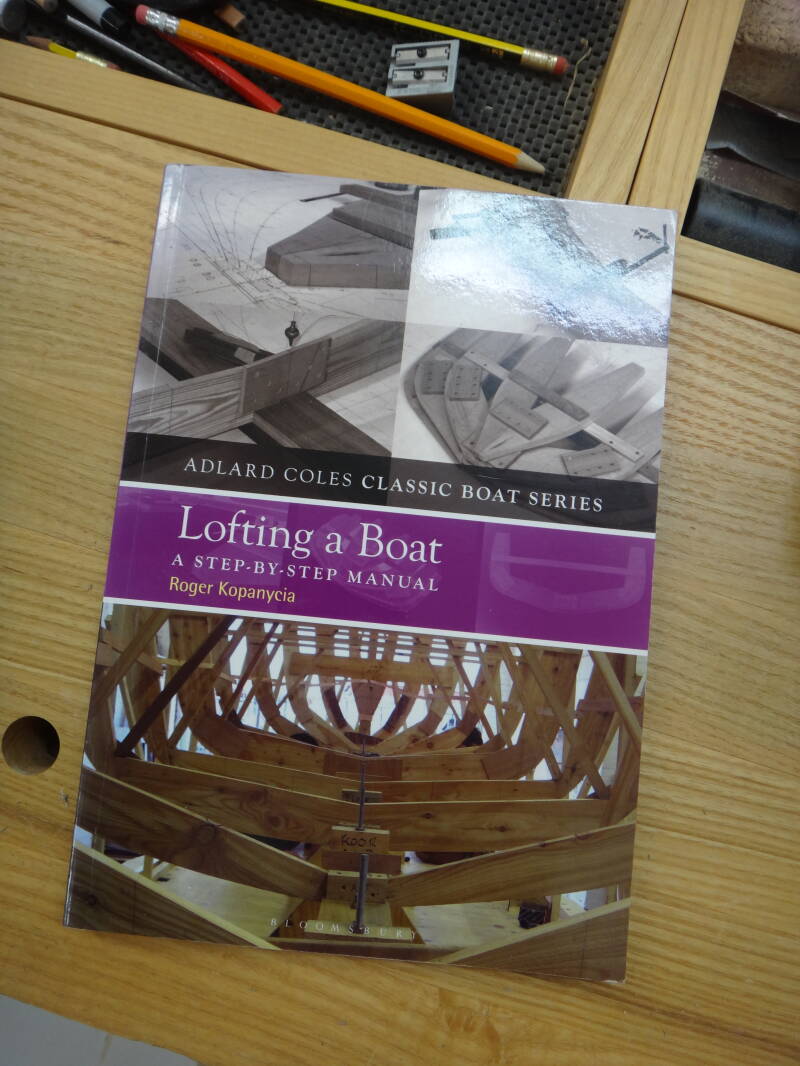
The first step was the lofting, something I had only previously done in a simplified manner when creating station moulds for canoes. The three books I was using tended to skirt around the subject but I found another excellent text by Roger Kopanycia that led me through the process in a detailed step-by-step way. I sometimes had to follow the instructions blindly, only understanding the principles when nearing the end of the procedure.
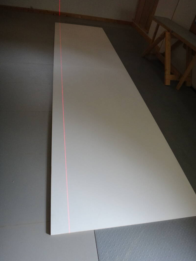
I didn't want to do the lofting on my floor and had slightly limited space, so joined two pieces of 8 x 4ft ply, painted them with white emulsion, and drew a keel line using a laser beam as a guide.
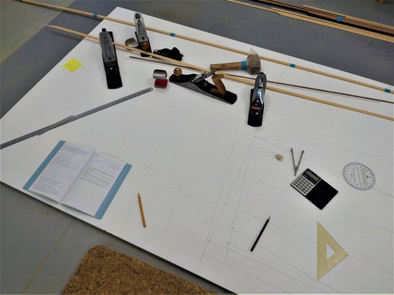
The limited space meant that the body, profile and half-breadth plans needed to be superimposed, so I used different coloured pencils for each. Even so, it became quite complicated.
A variety of heavy tools were used to hold the fairing batons in position before marking.
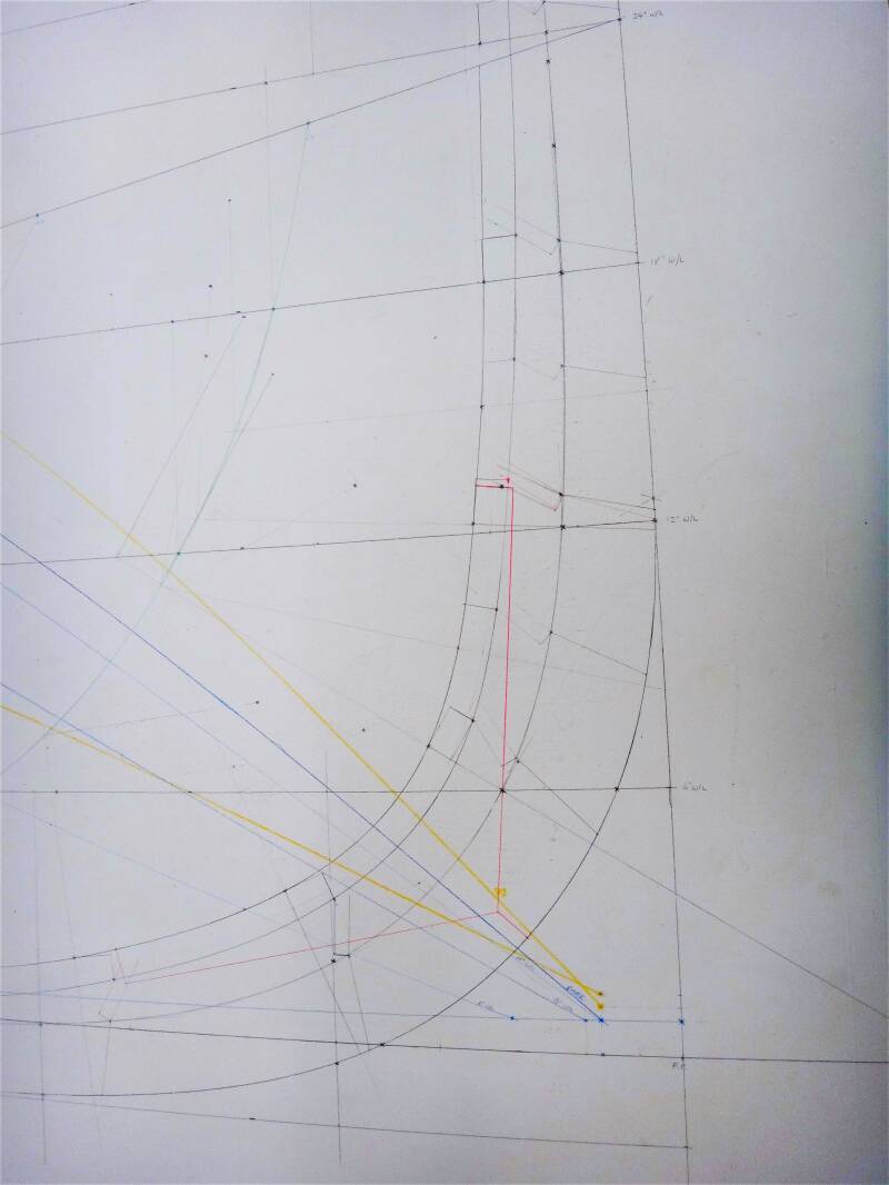
There were times when I wondered whether all of the detail and accuracy was really necessary, but cross-checking between the three sections did reveal a few small discrepancies which I was able to correct. There was a sense of achievement at the end but I wouldn't be able to do it again without following the book equally carefully.
As described in the book, I used the lofted plan to make cardboard patterns to show cross-sections of the stem and keel at numerous sites, as well as full-sized tracings of the stations and transom. The ply boards were then lifted and placed against my workshop wall, to create enough space to start building the boat.
The Wood
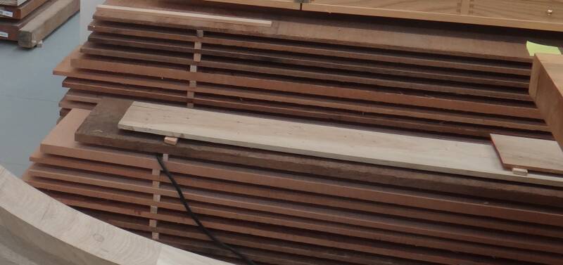
The plans suggested a combination of Oak (stem and frames), Douglas Fir (keel) and Western Red Cedar (planking). My biggest problem was sourcing the Western Red Cedar as I'd been advised that I would need 10" wide clear boards to allow for the curvature of the strakes. In the end I had to purchase the cedar wet and season it in my workshop for about 3 months. The other problem with cedar is the wide variation in colour, from a nice light brown to a dark muddy colour. I have decided to try to use just the lighter coloured boards and it will be an interesting challenge to get all I need from my available stock.
The Backbone
The first woodwork construction involved creating the components of the boat's backbone - the central spine including the stem, keel and transom.
The stem was designed to be constructed from blocks of oak, rather than laminated, and was glued with epoxy, later reinforced with copper rod peened over bronze washers.
I've always been impressed with the bonding strength of epoxy, usually being stronger than the wood itself. However, after building the stem I was told that it does not always form such a good bond with oak due to the tight grain. We'll see in due course but the copper rod will keep it fastened together. Here it is after preliminary shaping to the pattern from the lofting.

Here is the inside of the stem with the holes for the copper rods plugged.
I used multiple cardboard patterns of the stem cross-section to start creating the rebate for the planking.

The rebates were cut at each pattern site before joining them together.

The Douglas Fir keel is now having the oak apron bonded, fastened with silicon bronze screws, and the holes plugged.
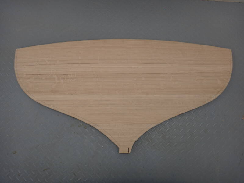
The transom is made up from several pieces, jointed with ply splines. A preliminary chamfer line is drawn, to be adjusted for accuracy later using a flexible batten over the building stations.
The stern knee was attached to the apron and the transom bonded and fixed with copper rods. I think it looks like a whales tail.
The centreboard slot has also been cut; one modification I have made from the original plans was to have a lifting centreboard rather than a daggerboard, so the slot is longer and the keel wider over the full length of the slot.

All the books stress the importance of the mystical 'stopwaters'. These little pegs cut across junctions with the aim of swelling and preventing water seeping past. I'm not convinced that they play a role at a joint that has been bonded with epoxy, but to do the job properly I put them in anyway. This is one being fitted at the stem.
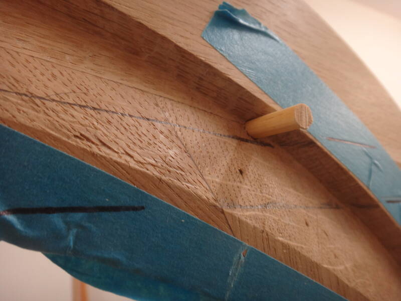
This has been trimmed back.
The Building Frame
Now it becomes controversial. There is great debate over whether to build a clinker boat the right way up, or upside down. There appears to be a geographical split, with boatbuilding schools in the UK teaching the 'right way up' method, and in the USA and Australia 'upside down'. The potential advantages of 'right way up' include a better view of the line of sheer and strakes, easier peening of roves from above, and avoidance of the need to invert the boat to insert the frames. The main benefit of 'upside down' is less time lying on your back, good visibility for adjusting the rebate and fitting the garboards, and easy access for creating plank 'landings'. I chatted with one UK builder whose main argument for 'right way up' seemed to be that it was 'the British way'. I thought a lot about the pros and cons for a single-handed builder and eventually decided that upside down would probably be easier for me - time will tell.
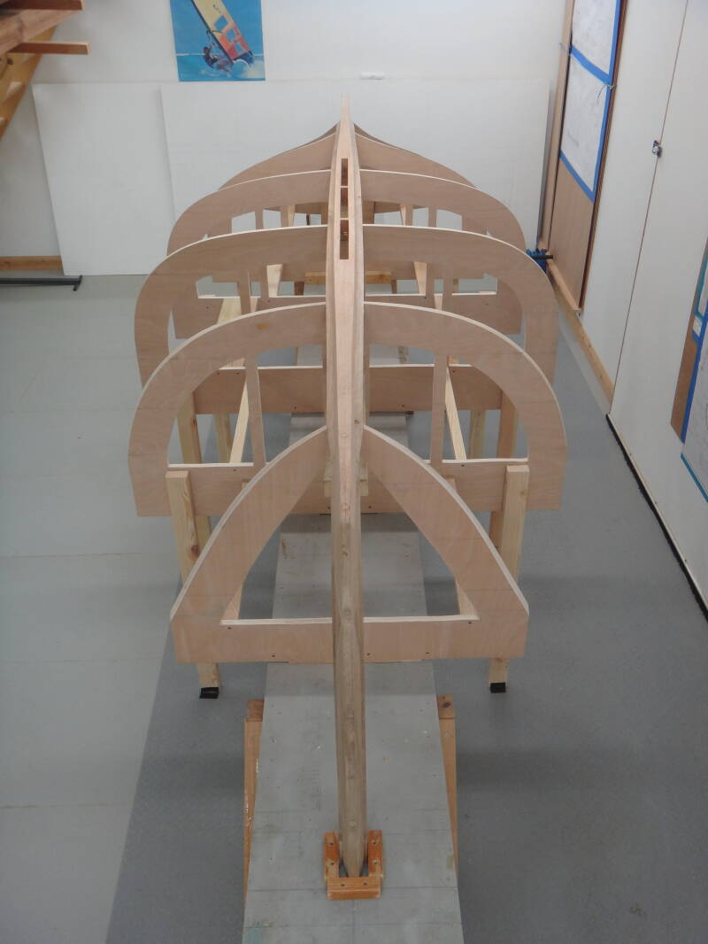
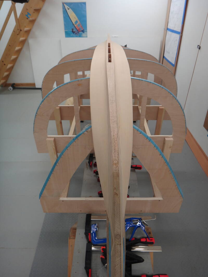
So, here is the building frame created on the strongback I have previously used for canoe and kayak building. The station frames are made from 20mm ply using lofted patterns and chamfered edges. After many careful measurements and laser alignment of the stations, the stem, keel and transom have been inverted and fixed in place. I didn't want to create screw holes for temporary fixation, as the books suggest, so have used hot melt glue which should clean off OK. You can now see the centreboard slot - two small sections have been left uncut to prevent the slot from widening during the planking process.
Lining Out
This process lays out the future positions of the planks using temporary battens, ensuring that they are 'fair' and suitably spaced. The spacing is not evenly distributed, planks being narrower at the bilges, and it needs to 'look right' - tricky when you haven't done it before and initially are not sure what to look for. It's likely that only boatbuilders will know whether or not you have been successful.
The Garboards
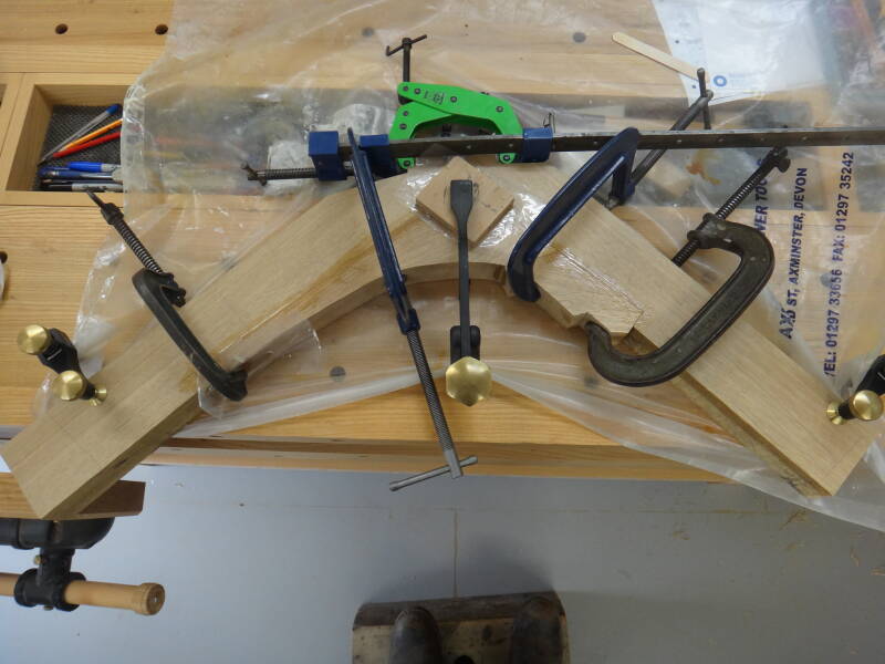
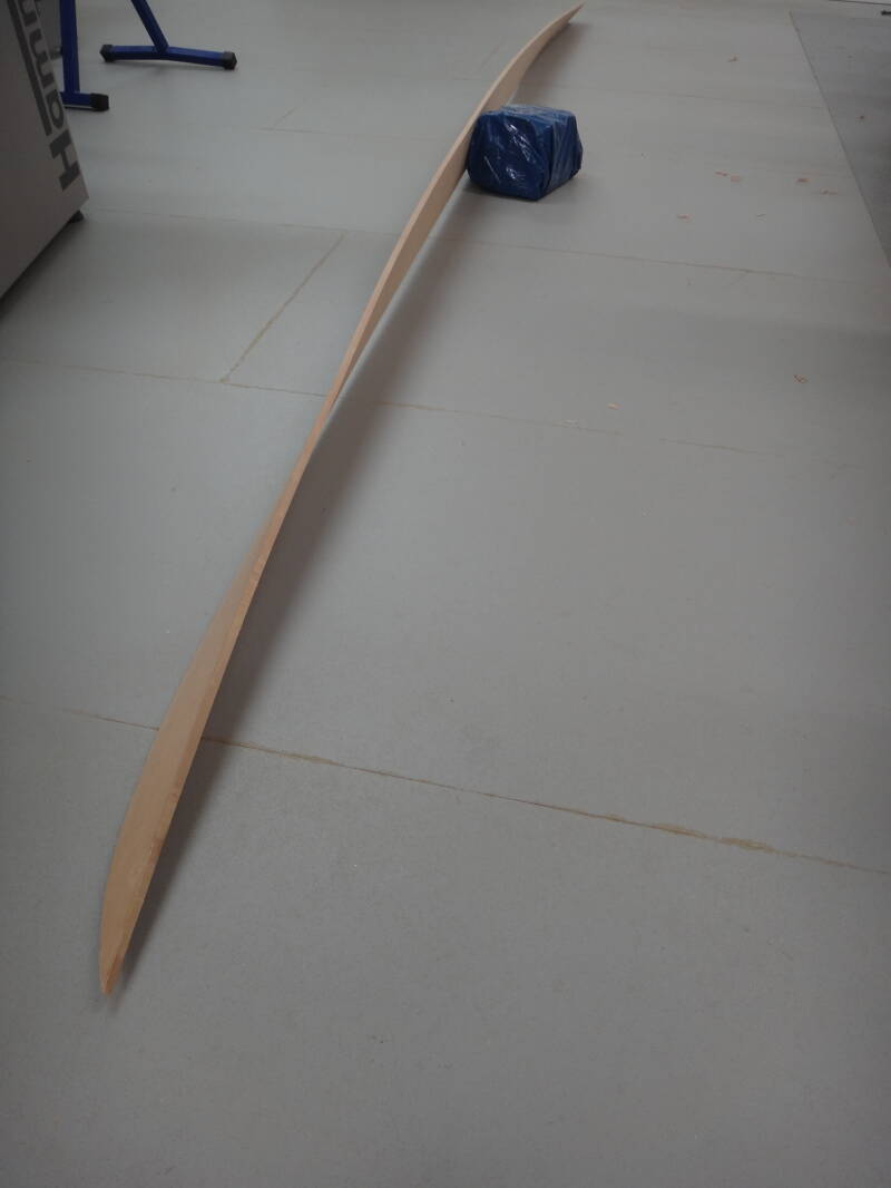
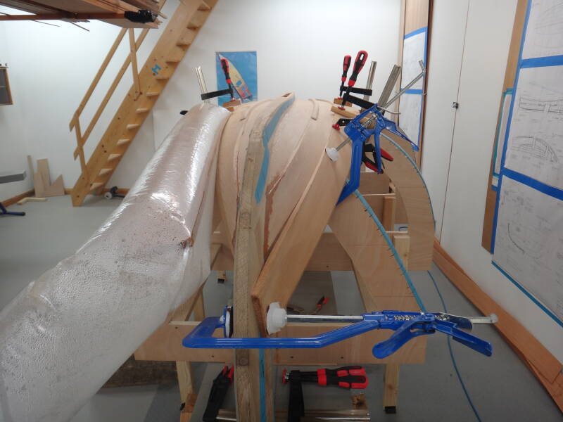
The first plank to be made and fitted is reputedly the most difficult - the garboard. It has to be fitted to the rebate from the stem, along the keel, and onto the transom. To add to the challenge, the board (in this case Western Red Cedar) has to be twisted along its length, requiring steaming. I had only previously done steam bending in a steam box but as the two ends needed to be steamed independently, while the other end was clamped, I used the 'boil in a bag' method, shown here. It only needed about 20 minutes which was a good as I didn't want my workshop too steamed up.
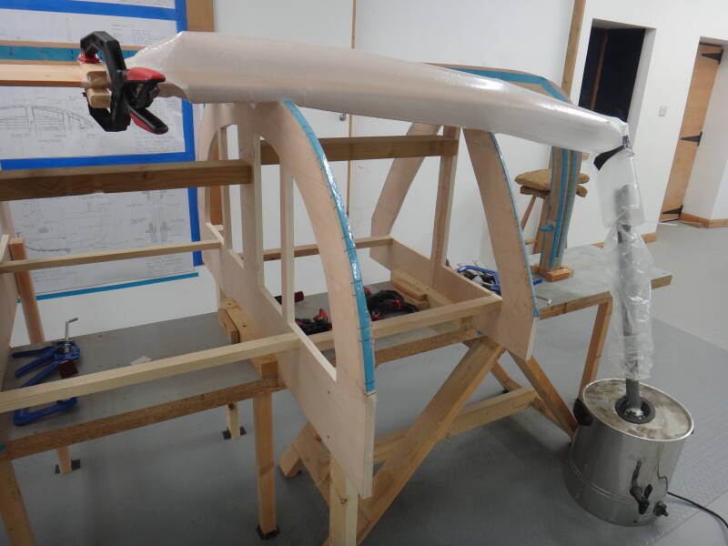
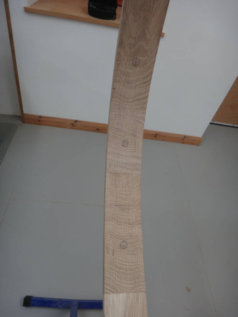
This picture shows the curvature of the shaped and bent garboard for the starboard side.
Now here some boatbuilders (including Paul Gartside!) may need to look away..... Traditionalists would never use any glue or flexible sealant when fixing planking, only using a wipe of linseed oil or varnish between planks. However, some more recent texts suggest that if you want a non-leaky boat there are points at which it is acceptable. I was striving for a non-leaky boat so, as recommended in Will Stirling's book (I'm passing the blame here) I glued the garboard and will use a little glue just at the stem and transom of subsequent planks - he suggests Gorilla glue. Ian Smith's book from the Sydney Wooden Boat School also recommends some Sikaflex flexible sealant between plank landings, so I'll give that a try too. As the flexibility between planks is needed to prevent planks from splitting, some flexible sealant doesn't seem unreasonable - they aren't going to move much anyway with all those nails and roves in place.
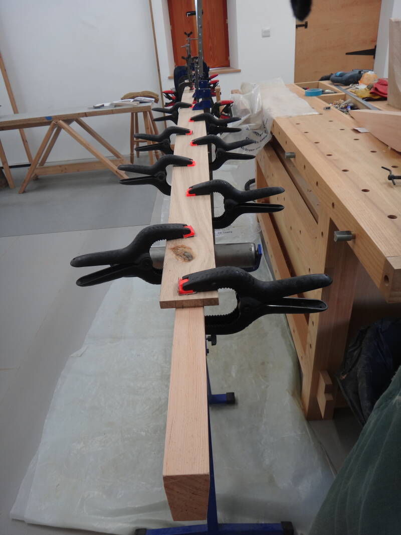
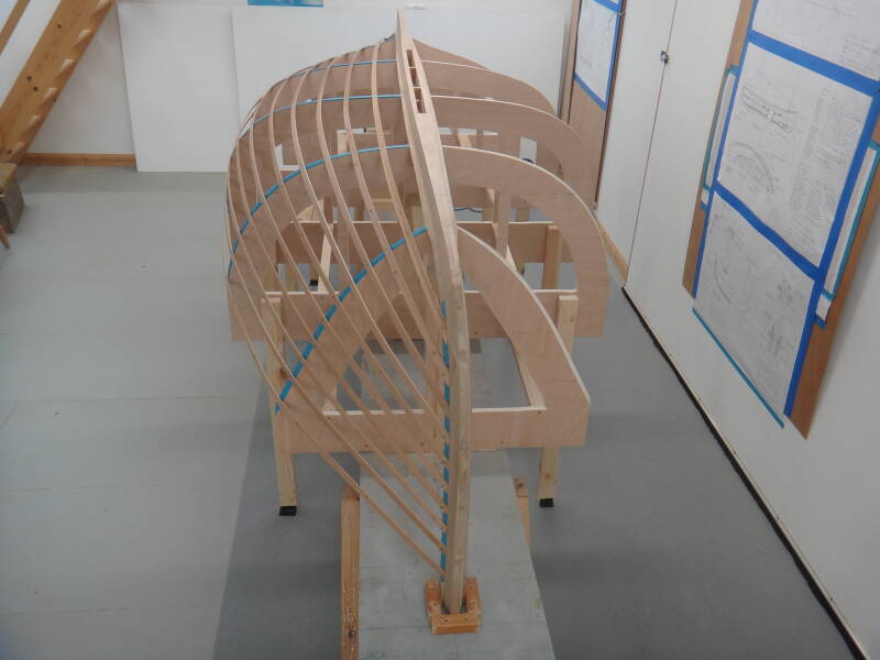
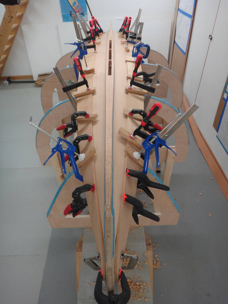
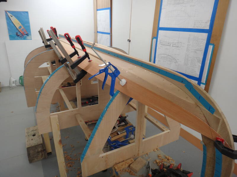
This image shows the first garboard in place and the second being clamped.
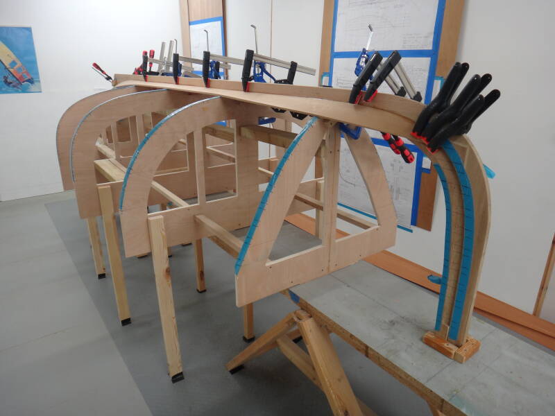
Here both garboards are in place with the fastenings yet to be inserted.
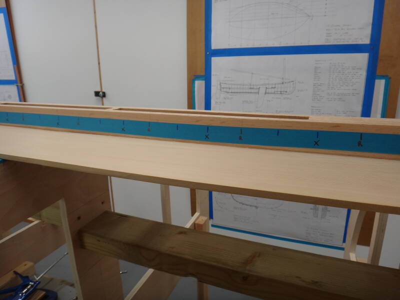
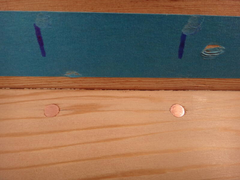
Planning out the position of the fastenings needs to be done at an early stage as it needs to account for the position of the frames (6" apart), with two nails going between each frame. In addition, there are oak rubrails protecting the first four planks, so some of the nails need to be used to also hold these in place. I put a strip of masking tape along each side of the keel and marked the position of each frame and nail site, and the ones to be used for fixing the rubrails. My first attempt resulted in some nail positions coinciding with the station frames, so I made adjustments to ensure that I could get access for fitting the roves.
The Planking
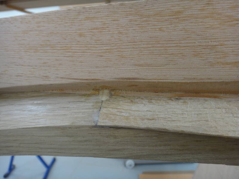
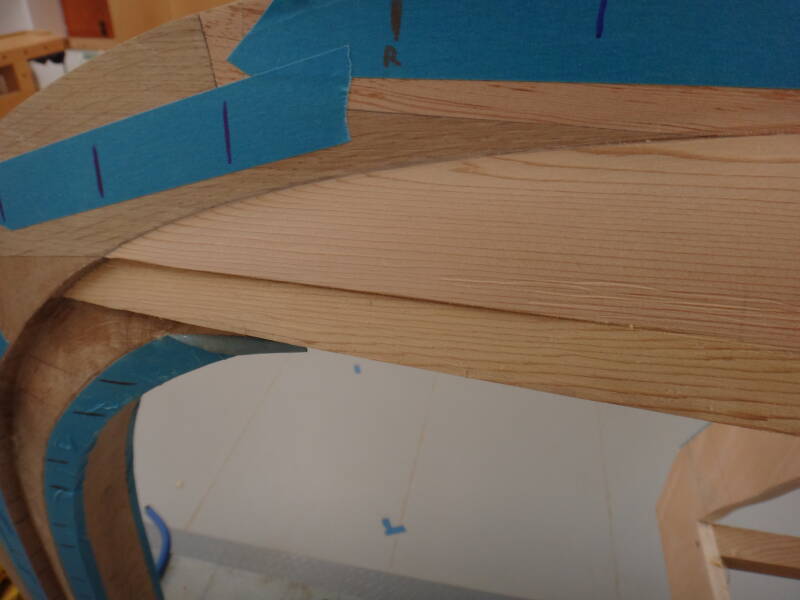
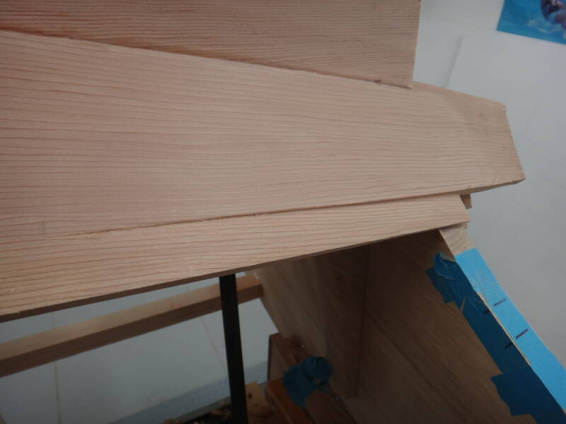
At the stem and transom the overlapping planks gradually merge together by creation of additional rebates on both the upper and lower board. These rebates are variously called 'geralds', 'jerralds' or 'jerrolds' and are tricky to do. Here is a picture of one at the stem and another at the transom. I find the Western Red Cedar very easy to plane/chisel/scrape because it is so light and soft, but the downside is that it is difficult to get sharp edges and marks extremely easily.
Now to the fastenings, something which in the early stages I have found difficult. Marking the cedar when hammering nails is a particular concern because the bruised wood can become a different colour when varnished - I've previously had real problems with this issue on a canoe build. Having practiced inserting a few nails and roves on the bench, I was surprised by how much hammering force was needed to get the nail through the rove - so much so that sometimes the 14g nail bent or twisted sideways and damaged the soft cedar. I persevered, but my first attempts when fixing the garboards caused a mixture of damage, stress and annoyance that was not compatible with a relaxing, therapeutic project! I decided that the hole in the copper roves was unnecessarily small and the only solution was to enlarge the hole with a twist drill - no small task with about 1500 roves needed.
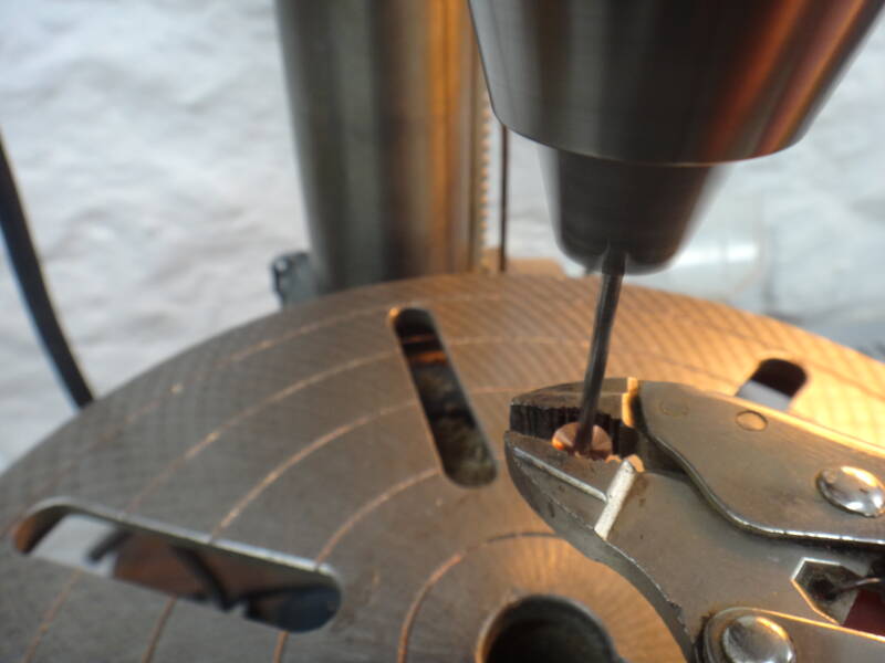
Nevertheless, this proved to be the answer, making an enormous difference and allowing the process to become manageable. I'm not sure whether others have found similar issues - I asked the suppliers and they had not had previous reports, so it may just be me.
Another early finding was that the drill size for the nail pilot holes was very critical if wanting to avoid bent copper nails. It doesn't matter too much when joining cedar to cedar, but if going through oak, it really does. All of my nail packets are now labelled with drill sizes to the nearest 0.1mm.
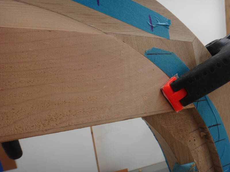
The shape of the second plank on one side was determined by 'spiling' (making a pattern) with some cheap 3mm ply, then cut out of cedar and copied for the other side. The second planks were put in place, the ends steamed to allow twisting, and clamped in place to dry overnight.
Having got the general shape there was quite a bit of fitting required at the stem, and the undersides of the boards needed a rebate to match the jerralds at each end.
The second strakes were then fastened and the oak rubrail attached in the middle section.
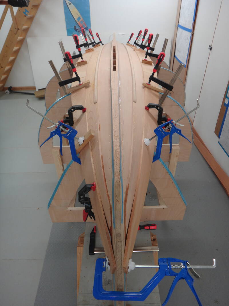
Here the 3mm spiling ply is in position to mark out the shape of the third board.
One plank has been steamed at the stem end and is clamped in place, the other is being steamed.
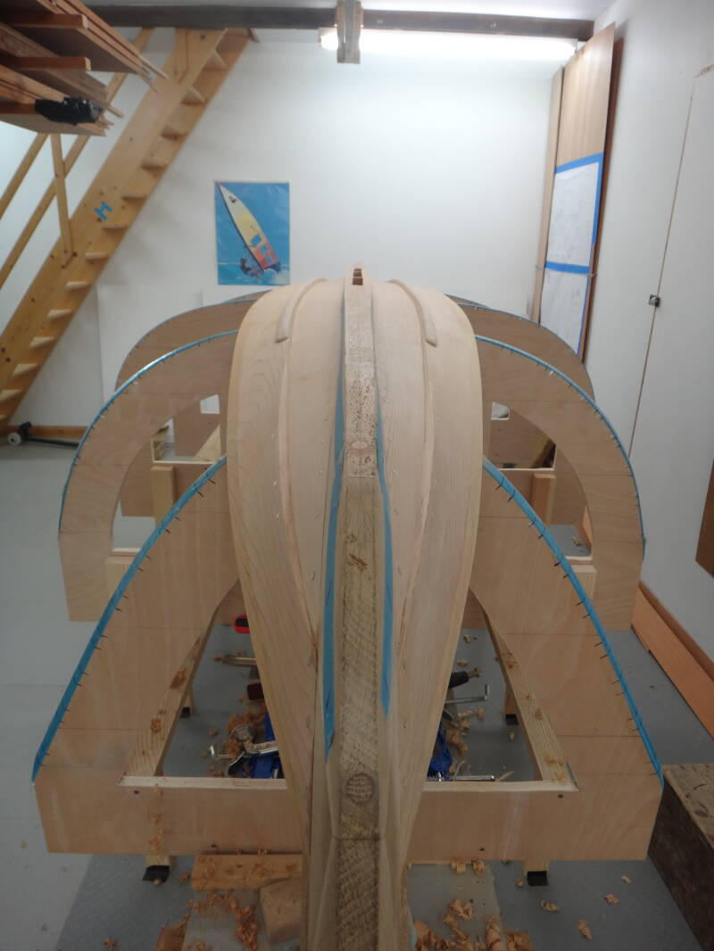
Both of the third planks are now held in shape, ready for final shaping when dry.
And so on. With my slow and steady progress, together with plenty of breaks for sailing other boats, I anticipate another few months of planking before turning the boat over and starting on the inside. I will report more in due course.
Create Your Own Website With Webador