Part 4
Starting the fit-out
Although I now had something that resembled a boat, numerous varied and interesting tasks remained to make it into a usable sailing dinghy. I set about making various bits and pieces in gaps between sailing trips over the summer, so didn't always follow a logical sequence in the order of work.
First, though, I needed to strengthen the 'corners' with a breast hook at the bow and quarter knees in the stern. I searched through my wood store and found some old oak that had reasonably suitable grain patterns, even if not perfect 'crooks'. Having always used lightweight construction methods in the past, these big lumps of wood seem like overkill to me, but they should look nice when varnished.
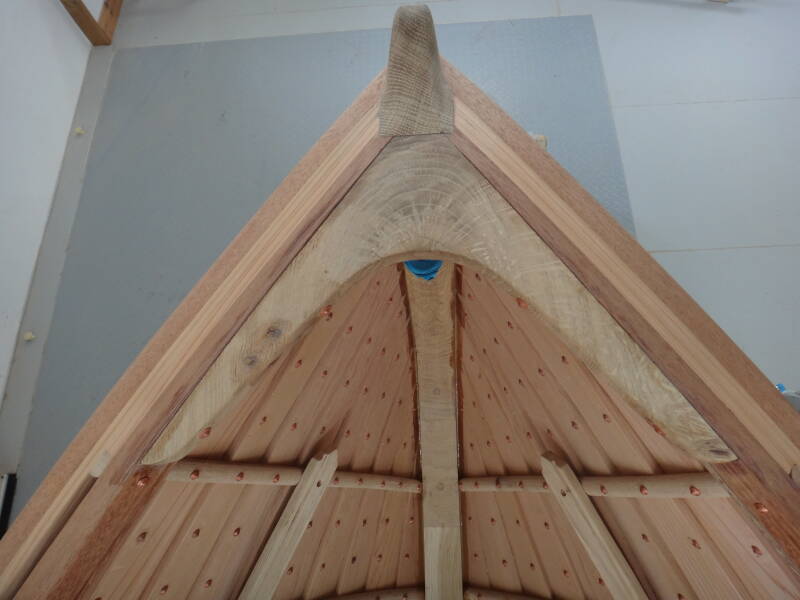
The oak breast hook glued and through-nailed in place.
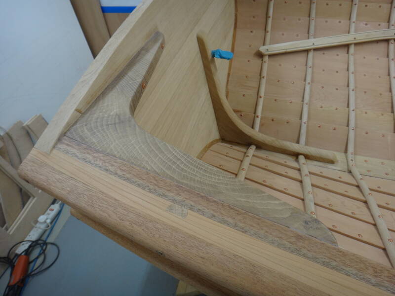
One of the oak quarter knees.
The oak 'rising' is the longitudinal strip of timber that supports the stern benches and thwarts so must be level. I used a laser level to mark out the position before steaming and clamping the shaped oak. Clamping was a challenge due to insufficient jaw depth on most of my clamps, so wooden offcuts were clamped between the rising and gunwale to extend the jaws. Bronze screws fixed the rising to each frame and the screw heads were plugged.
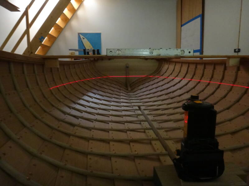
With the boat flat, a laser level was used to mark the position of the rising.
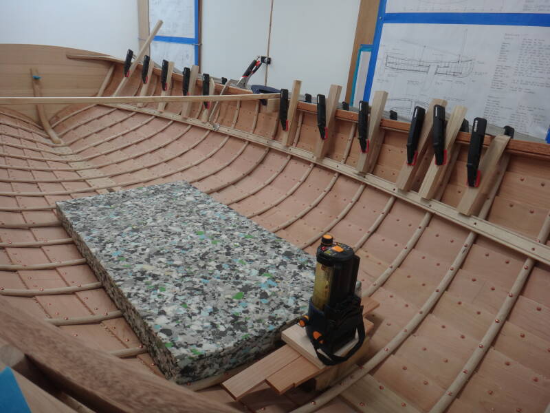
The rising clamped in place before being drilled and screwed to the frames. Wooden offcuts extend the clamp jaws.
Another oak strip is needed on each side to act as the margin for the floorboards (sometimes called sole boards) and to hold them in place. This proved even more challenging than the risings as it required a substantial edge-bend on the oak. Despite generous steaming both of my first pieces broke. However, my second attempts with straighter grained oak were successful after creating the bend with clamps on my workbench. When cooled and dry, the bent pieces were fitted to the boat and screwed to the frames.
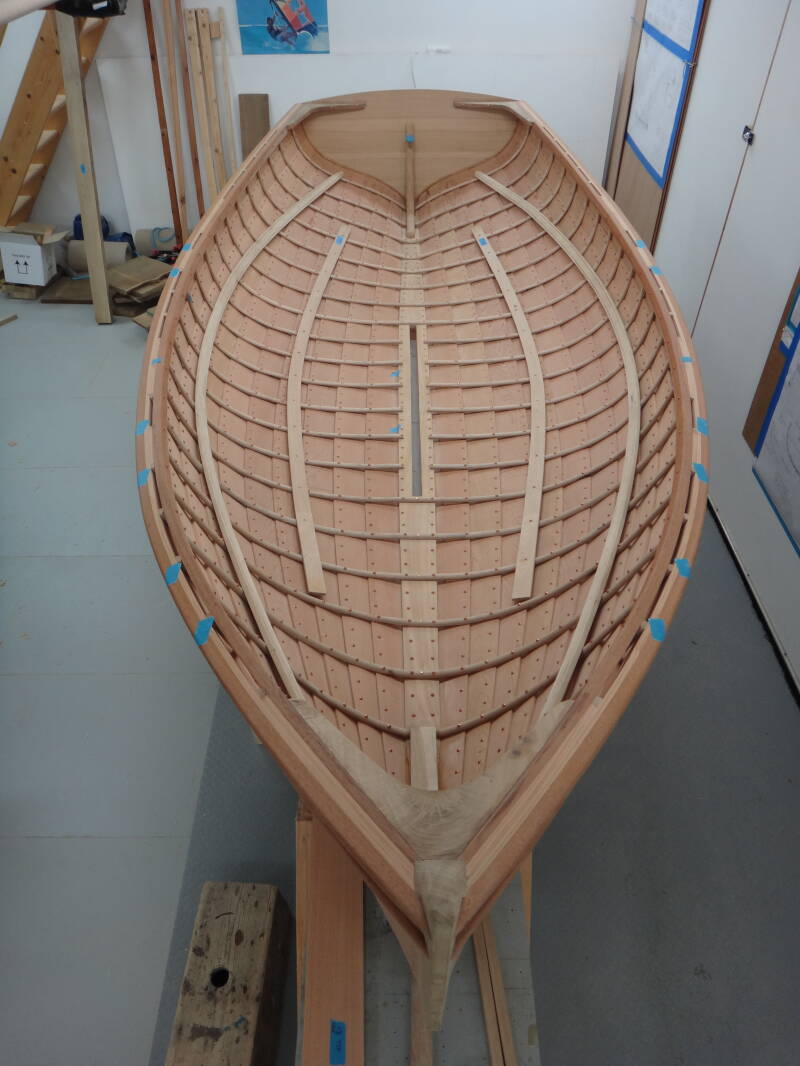
Risings and floorboard margins in place.
My boat differs from the original plans by using a lifting centreboard rather than a daggerboard - this was recommended by the designer, Paul Gartside. I made the centreboard case from Douglas fir with oak end ledges that extend down through the keel slot. I added a splines to these joints in addition to glueing and screwing, to reduce the chances of leakage. A flange along the sides will allow the case to be firmly screwed down to the keel in due course.
When working through these tasks you realise how many steps are interdependent. For example, the top of the centreboard case must align with the bottom of the central thwart, and this in turn is governed by the position of the rising. This means that final fitting is delayed until you are sure it is all correctly sized and positioned. This may be beneficial as final sanding and preliminary finishing can be done with good access to the inside of the boat and some fittings added later. I expect this sequencing comes naturally to a professional boatbuilder but for an amateur like me, much time is spent in thought.
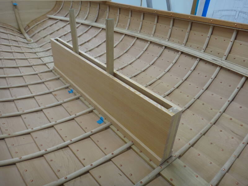
The centreboard casing being trial fitted to the keel. Temporary spacers extending into the keel slot ensure that it is centred along its full length.
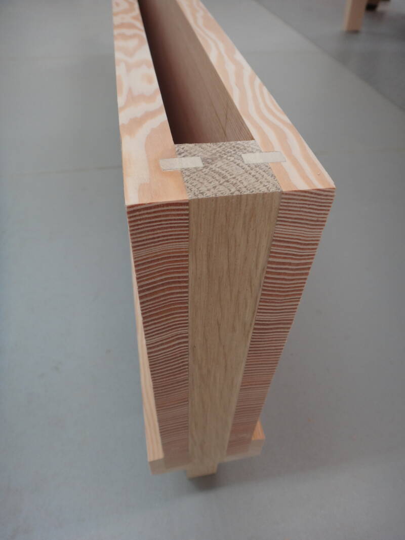
The end of the centreboard case showing the splined joints.
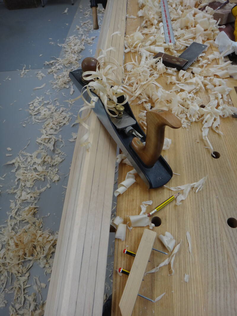
With the centreboard case on the bench, it seemed a suitable time to make and check the fit of the centreboard. I used some jointed Douglas fir with some attractively grained yew to add a little bling to the sides of the handle. I made cardboard templates of appropriately sized NACA 0010 aerofoils (available online) to help with the shaping, and produced a satisfying pile of shavings with plane and spokeshave. I then sheathed the centreboard with glass and epoxy to minimise the chances of distortion. I'll fit a centreboard brake as I've found this to work well on my previous boats.
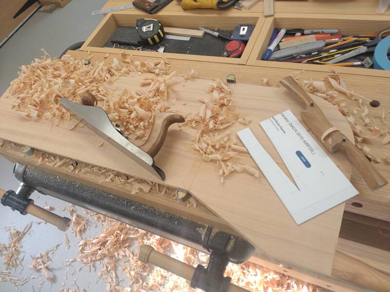
The centreboard being shaped with the help of a template.
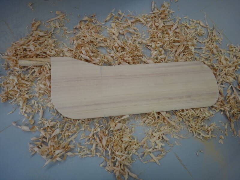
Most shaping completed
Each thwart is positioned to butt up against two frames and fitting is easier if you make a template first using battens and thin ply held together with hot melt glue. After cutting the thwarts I added a bead to both edges using an old Stanley no 66 hand beading tool found online.
Above: Temporary templates to obtain the size and shape of the thwarts.
Right: A beading tool used at front and back of the thwart.
Templates placed on the stock to transfer the shape.
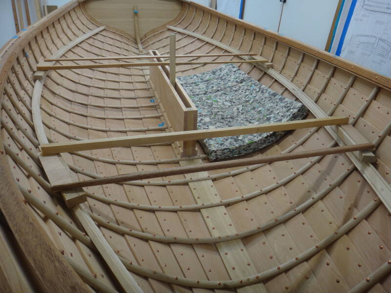
I next turned my attention to a small raised section of flooring near the bow, and the mast step. This required the construction of three supports that needed to fit accurately to the contours of the central section of the hull. I cut cardboard templates for the initial shape and then spent a long time carving and adjusting. Limber holes (for water drainage) were incorporated at each junction and each support will be glued and screwed to the keel and planks. The oak mast step was also shaped but the hole for the bottom of the mast won't be cut until later.
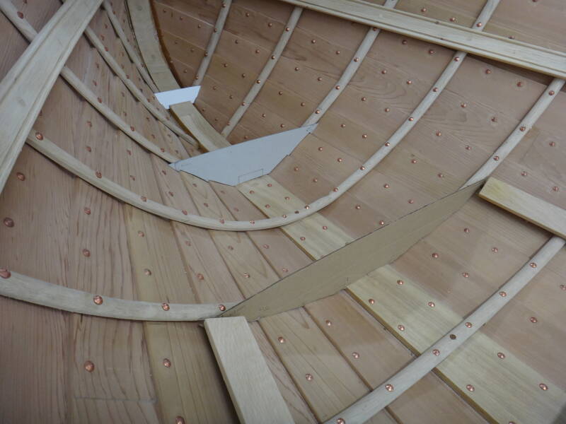
Cardboard templates for the three supports for the front section of flooring and the mast step.
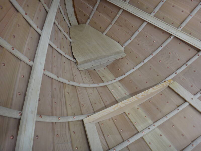
The supports and mast step temporarily in position.
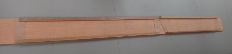
It may seem out of sequence but I have also been working on the spars so that I could give bend measurements to the sailmaker who is due to start making my balanced lugsail shortly. I'm using Sitka spruce and have made a two-part mast so that I could hollow the centre and reduce a little weight. I did the hollowing on a spindle moulder so the recess was the same width all the way up, despite the tapering of the mast. This meant that the wall thickness reduced towards the top but I ensured that it did not get less than approximately 25% of the mast diameter. I was reassured when, part way through this process, I read the article by Julian Wolfram in Watercraft (165, pp 49-51, 2024) which gave me the impression that my spars could be thinner than specified on the plans and therefore lighter. Having queried this with Paul Gartside (he is getting used to hearing from me) he advised that if I removed an extra 1/8th inch from the diameter of the boom and yard I would probably be fine!
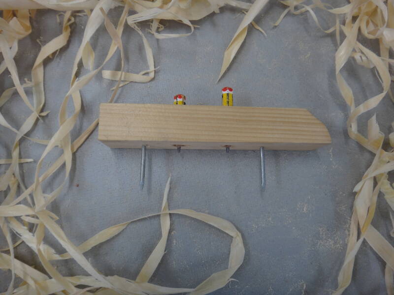
The two halves of the mast were bonded with slightly thickened epoxy and then it was tapered. Rounding was started by turning the mast from square into eight-sided using a spar gauge. I made a gauge from a scrap of wood with careful spacing of two nails and two pencils. If the ratio of spaces between nail and pencil at each end, and pencil to pencil in the middle, is 7:10:7, then the pencils will mark the lines needed to create an eight-sided spar. When the gauge is slid along each surface and angled so that the nails are held firmly in contact with the sides of the spar, the taper of the sides will be taken into account.
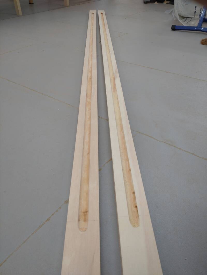
Left: The two halves of the mast, hollowed to reduce weight, before bonding, tapering and rounding.
Above: My spar gauge made using two nails and the stubs of two pencils.
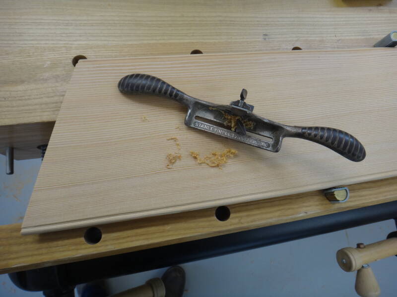
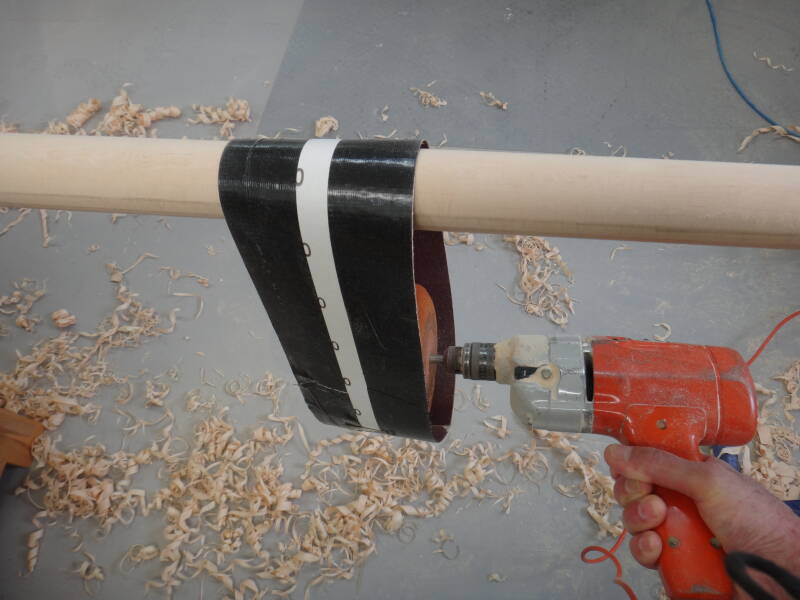
The corners of the spar are then planed off, down to the pencil marks on adjacent sides - good exercise with lots of perspiration. The corners of the eight-sided spar are then rounded off with the plane, at which point the dusty mess with sandpaper starts. I used a very crude system to drive an inside-out sandpaper ring using an old power drill, and the resulting Sitka spruce dust reached every corner and surface in my workshop. A good mask is essential and I would recommend doing this job outside if at all possible, or you waste a few hours cleaning up.
Left: The mast marked up with a spar gauge and planing to 8-sided started.
Above: A ring of sandpaper rotated by a power drill, used for preliminary rounding.
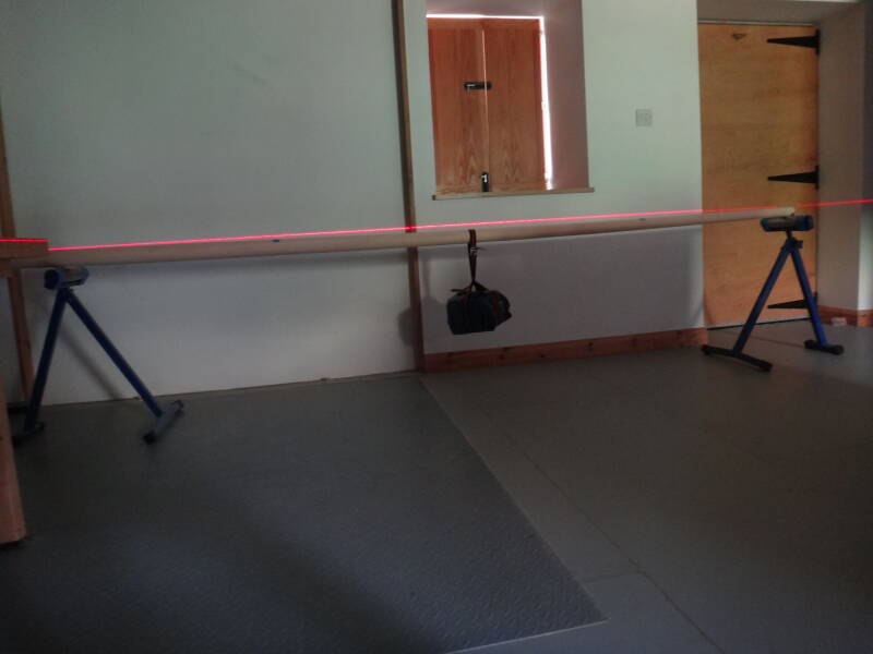
After completing the spars I needed to measure their bending characteristics so that I could inform the sailmaker and he can take this into account when cutting the sail. I used the method described in Todd Bradshaw's excellent book 'Canoe Rig, The Essence and the Art'. I know I'm not making a canoe but the principles are the same. The spars are supported at each end (with the side that will be against the sail on top) and a weight equal to one-third of the sail's square footage in pounds is suspended from the middle. I used a laser beam to take deflection measurements at the midpoint and at 25% from each end.

Left: Mast, boom and yard together with a pile of Sitka spruce shavings.
Above: The boom supported at its ends and weighted in the middle, with a laser beam used to take bend measurements.
Next time: More work on the fit-out, followed by sanding, cleaning up and varnishing.
Create Your Own Website With Webador